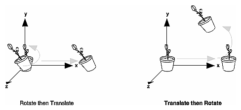
Viewing and Modeling TransformationsViewing and modeling transformations are inextricably related in OpenGL and are in fact combined into a single modelview matrix. (See "A Simple Example: Drawing a Cube.") One of the toughest problems newcomers to computer graphics face is understanding the effects of combined three-dimensional transformations. As you've already seen, there are alternative ways to think about transformations - do you want to move the camera in one direction, or move the object in the opposite direction? Each way of thinking about transformations has advantages and disadvantages, but in some cases one way more naturally matches the effect of the intended transformation. If you can find a natural approach for your particular application, it's easier to visualize the necessary transformations and then write the corresponding code to specify the matrix manipulations. The first part of this section discusses how to think about transformations; later, specific commands are presented. For now, we use only the matrix-manipulation commands you've already seen. Finally, keep in mind that you must call glMatrixMode() with GL_MODELVIEW as its argument prior to performing modeling or viewing transformations. Thinking about TransformationsLet's start with a simple case of two transformations: a 45-degree counterclockwise rotation about the origin around the z-axis, and a translation down the x-axis. Suppose that the object you're drawing is small compared to the translation (so that you can see the effect of the translation), and that it's originally located at the origin. If you rotate the object first and then translate it, the rotated object appears on the x-axis. If you translate it down the x-axis first, however, and then rotate about the origin, the object is on the line y=x, as shown in Figure 3-4. In general, the order of transformations is critical. If you do transformation A and then transformation B, you almost always get something different than if you do them in the opposite order.
Figure 3-4 : Rotating First or Translating First Now let's talk about the order in which you specify a series of transformations. All viewing and modeling transformations are represented as 4 × 4 matrices. Each successive glMultMatrix*() or transformation command multiplies a new 4 × 4 matrix M by the current modelview matrix C to yield CM. Finally, vertices v are multiplied by the current modelview matrix. This process means that the last transformation command called in your program is actually the first one applied to the vertices: CMv. Thus, one way of looking at it is to say that you have to specify the matrices in the reverse order. Like many other things, however, once you've gotten used to thinking about this correctly, backward will seem like forward. Consider the following code sequence, which draws a single point using three transformations: glMatrixMode(GL_MODELVIEW);
glLoadIdentity();
glMultMatrixf(N); /* apply transformation N */ glMultMatrixf(M); /* apply transformation M */ glMultMatrixf(L); /* apply transformation L */ glBegin(GL_POINTS);
glVertex3f(v); /* draw transformed vertex v */ glEnd();
With this code, the modelview matrix successively contains I, N, NM, and finally NML, where I represents the identity matrix. The transformed vertex is NMLv. Thus, the vertex transformation is N(M(Lv)) - that is, v is multiplied first by L, the resulting Lv is multiplied by M, and the resulting MLv is multiplied by N. Notice that the transformations to vertex v effectively occur in the opposite order than they were specified. (Actually, only a single multiplication of a vertex by the modelview matrix occurs; in this example, the N, M, and L matrices are already multiplied into a single matrix before it's applied to v.) Grand, Fixed Coordinate SystemThus, if you like to think in terms of a grand, fixed coordinate system - in which matrix multiplications affect the position, orientation, and scaling of your model - you have to think of the multiplications as occurring in the opposite order from how they appear in the code. Using the simple example shown on the left side of Figure 3-4 (a rotation about the origin and a translation along the x-axis), if you want the object to appear on the axis after the operations, the rotation must occur first, followed by the translation. To do this, you'll need to reverse the order of operations, so the code looks something like this (where R is the rotation matrix and T is the translation matrix): glMatrixMode(GL_MODELVIEW);
glLoadIdentity();
glMultMatrixf(T); /* translation */ glMultMatrixf(R); /* rotation */ draw_the_object();
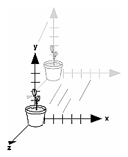
Moving a Local Coordinate SystemAnother way to view matrix multiplications is to forget about a grand, fixed coordinate system in which your model is transformed and instead imagine that a local coordinate system is tied to the object you're drawing. All operations occur relative to this changing coordinate system. With this approach, the matrix multiplications now appear in the natural order in the code. (Regardless of which analogy you're using, the code is the same, but how you think about it differs.) To see this in the translation-rotation example, begin by visualizing the object with a coordinate system tied to it. The translation operation moves the object and its coordinate system down the x-axis. Then, the rotation occurs about the (now-translated) origin, so the object rotates in place in its position on the axis. This approach is what you should use for applications such as articulated robot arms, where there are joints at the shoulder, elbow, and wrist, and on each of the fingers. To figure out where the tips of the fingers go relative to the body, you'd like to start at the shoulder, go down to the wrist, and so on, applying the appropriate rotations and translations at each joint. Thinking about it in reverse would be far more confusing. This second approach can be problematic, however, in cases where scaling occurs, and especially so when the scaling is nonuniform (scaling different amounts along the different axes). After uniform scaling, translations move a vertex by a multiple of what they did before, since the coordinate system is stretched. Nonuniform scaling mixed with rotations may make the axes of the local coordinate system nonperpendicular. As mentioned earlier, you normally issue viewing transformation commands in your program before any modeling transformations. This way, a vertex in a model is first transformed into the desired orientation and then transformed by the viewing operation. Since the matrix multiplications must be specified in reverse order, the viewing commands need to come first. Note, however, that you don't need to specify either viewing or modeling transformations if you're satisfied with the default conditions. If there's no viewing transformation, the "camera" is left in the default position at the origin, pointed toward the negative z-axis; if there's no modeling transformation, the model isn't moved, and it retains its specified position, orientation, and size. Since the commands for performing modeling transformations can be used to perform viewing transformations, modeling transformations are discussed first, even if viewing transformations are actually issued first. This order for discussion also matches the way many programmers think when planning their code: Often, they write all the code necessary to compose the scene, which involves transformations to position and orient objects correctly relative to each other. Next, they decide where they want the viewpoint to be relative to the scene they've composed, and then they write the viewing transformations accordingly. Modeling TransformationsThe three OpenGL routines for modeling transformations are glTranslate*(), glRotate*(), and glScale*(). As you might suspect, these routines transform an object (or coordinate system, if you're thinking of it that way) by moving, rotating, stretching, shrinking, or reflecting it. All three commands are equivalent to producing an appropriate translation, rotation, or scaling matrix, and then calling glMultMatrix*() with that matrix as the argument. However, these three routines might be faster than using glMultMatrix*(). OpenGL automatically computes the matrices for you. (See Appendix F if you're interested in the details.) In the command summaries that follow, each matrix multiplication is described in terms of what it does to the vertices of a geometric object using the fixed coordinate system approach, and in terms of what it does to the local coordinate system that's attached to an object. Translatevoid glTranslate{fd}(TYPEx, TYPE y, TYPEz); Multiplies the current matrix by a matrix that moves (translates) an object by the given x, y, and z values (or moves the local coordinate system by the same amounts). Figure 3-5 shows the effect of glTranslate*().
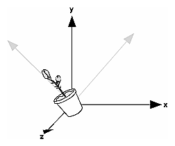
Figure 3-5 : Translating an Object Note that using (0.0, 0.0, 0.0) as the argument for glTranslate*() is the identity operation - that is, it has no effect on an object or its local coordinate system. Rotatevoid glRotate{fd}(TYPE angle, TYPE x, TYPE y, TYPE z); Multiplies the current matrix by a matrix that rotates an object (or the local coordinate system) in a counterclockwise direction about the ray from the origin through the point (x, y, z). The angle parameter specifies the angle of rotation in degrees. The effect of glRotatef(45.0, 0.0, 0.0, 1.0), which is a rotation of 45 degrees about the z-axis, is shown in Figure 3-6.
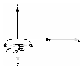
Figure 3-6 : Rotating an Object Note that an object that lies farther from the axis of rotation is more dramatically rotated (has a larger orbit) than an object drawn near the axis. Also, if the angle argument is zero, the glRotate*() command has no effect. Scalevoid glScale{fd}(TYPEx, TYPE y, TYPEz); Multiplies the current matrix by a matrix that stretches, shrinks, or reflects an object along the axes. Each x, y, and z coordinate of every point in the object is multiplied by the corresponding argument x, y, or z. With the local coordinate system approach, the local coordinate axes are stretched, shrunk, or reflected by the x, y, and z factors, and the associated object is transformed with them. Figure 3-7 shows the effect of glScalef(2.0, -0.5, 1.0).
Figure 3-7 : Scaling and Reflecting an Object glScale*() is the only one of the three modeling transformations that changes the apparent size of an object: Scaling with values greater than 1.0 stretches an object, and using values less than 1.0 shrinks it. Scaling with a -1.0 value reflects an object across an axis. The identity values for scaling are (1.0, 1.0, 1.0). In general, you should limit your use of glScale*() to those cases where it is necessary. Using glScale*() decreases the performance of lighting calculations, because the normal vectors have to be renormalized after transformation. Note: A scale value of zero collapses all object coordinates along that axis to zero. It's usually not a good idea to do this, because such an operation cannot be undone. Mathematically speaking, the matrix cannot be inverted, and inverse matrices are required for certain lighting operations. (See Chapter 5.) Sometimes collapsing coordinates does make sense, however; the calculation of shadows on a planar surface is a typical application. (See "Shadows" in Chapter 14.) In general, if a coordinate system is to be collapsed, the projection matrix should be used rather than the modelview matrix. A Modeling Transformation Code ExampleExample 3-2 is a portion of a program that renders a triangle four times, as shown in Figure 3-8. These are the four transformed triangles.
Figure 3-8 : Modeling Transformation Example Example 3-2 : Using Modeling Transformations: model.c glLoadIdentity(); glColor3f(1.0, 1.0, 1.0); draw_triangle(); /* solid lines */ glEnable(GL_LINE_STIPPLE); /* dashed lines */ glLineStipple(1, 0xF0F0); glLoadIdentity(); glTranslatef(-20.0, 0.0, 0.0); draw_triangle(); glLineStipple(1, 0xF00F); /*long dashed lines */ glLoadIdentity(); glScalef(1.5, 0.5, 1.0); draw_triangle(); glLineStipple(1, 0x8888); /* dotted lines */ glLoadIdentity(); glRotatef (90.0, 0.0, 0.0, 1.0); draw_triangle (); glDisable (GL_LINE_STIPPLE); Note the use of glLoadIdentity() to isolate the effects of modeling transformations; initializing the matrix values prevents successive transformations from having a cumulative effect. Even though using glLoadIdentity() repeatedly has the desired effect, it may be inefficient, because you may have to respecify viewing or modeling transformations. (See "Manipulating the Matrix Stacks" for a better way to isolate transformations.) Note: Sometimes, programmers who want a continuously rotating object attempt to achieve this by repeatedly applying a rotation matrix that has small values. The problem with this technique is that because of round-off errors, the product of thousands of tiny rotations gradually drifts away from the value you really want (it might even become something that isn't a rotation). Instead of using this technique, increment the angle and issue a new rotation command with the new angle at each update step. Viewing TransformationsA viewing transformation changes the position and orientation of the viewpoint. If you recall the camera analogy, the viewing transformation positions the camera tripod, pointing the camera toward the model. Just as you move the camera to some position and rotate it until it points in the desired direction, viewing transformations are generally composed of translations and rotations. Also remember that to achieve a certain scene composition in the final image or photograph, you can either move the camera or move all the objects in the opposite direction. Thus, a modeling transformation that rotates an object counterclockwise is equivalent to a viewing transformation that rotates the camera clockwise, for example. Finally, keep in mind that the viewing transformation commands must be called before any modeling transformations are performed, so that the modeling transformations take effect on the objects first. You can manufacture a viewing transformation in any of several ways, as described next. You can also choose to use the default location and orientation of the viewpoint, which is at the origin, looking down the negative z-axis.
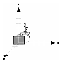
Using glTranslate*() and glRotate*()When you use modeling transformation commands to emulate viewing transformations, you're trying to move the viewpoint in a desired way while keeping the objects in the world stationary. Since the viewpoint is initially located at the origin and since objects are often most easily constructed there as well (see Figure 3-9), in general you have to perform some transformation so that the objects can be viewed. Note that, as shown in the figure, the camera initially points down the negative z-axis. (You're seeing the back of the camera.)
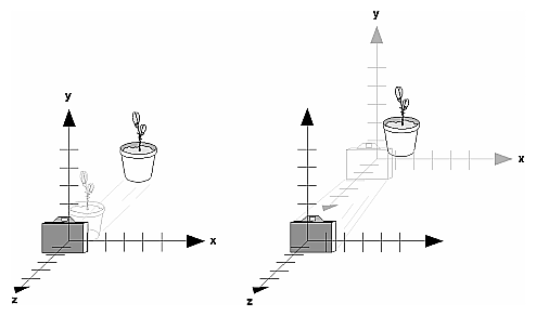
Figure 3-9 : Object and Viewpoint at the Origin In the simplest case, you can move the viewpoint backward, away from the objects; this has the same effect as moving the objects forward, or away from the viewpoint. Remember that by default forward is down the negative z-axis; if you rotate the viewpoint, forward has a different meaning. So, to put 5 units of distance between the viewpoint and the objects by moving the viewpoint, as shown in Figure 3-10, use glTranslatef(0.0, 0.0, -5.0); This routine moves the objects in the scene -5 units along the z axis. This is also equivalent to moving the camera +5 units along the z axis.
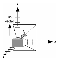
Figure 3-10 : Separating the Viewpoint and the Object Now suppose you want to view the objects from the side. Should you issue a rotate command before or after the translate command? If you're thinking in terms of a grand, fixed coordinate system, first imagine both the object and the camera at the origin. You could rotate the object first and then move it away from the camera so that the desired side is visible. Since you know that with the fixed coordinate system approach, commands have to be issued in the opposite order in which they should take effect, you know that you need to write the translate command first in your code and follow it with the rotate command. Now let's use the local coordinate system approach. In this case, think about moving the object and its local coordinate system away from the origin; then, the rotate command is carried out using the now-translated coordinate system. With this approach, commands are issued in the order in which they're applied, so once again the translate command comes first. Thus, the sequence of transformation commands to produce the desired result is glTranslatef(0.0, 0.0, -5.0); glRotatef(90.0, 0.0, 1.0, 0.0); If you're having trouble keeping track of the effect of successive matrix multiplications, try using both the fixed and local coordinate system approaches and see whether one makes more sense to you. Note that with the fixed coordinate system, rotations always occur about the grand origin, whereas with the local coordinate system, rotations occur about the origin of the local system. You might also try using the gluLookAt() utility routine described in the next section. Using the gluLookAt() Utility RoutineOften, programmers construct a scene around the origin or some other convenient location, then they want to look at it from an arbitrary point to get a good view of it. As its name suggests, the gluLookAt() utility routine is designed for just this purpose. It takes three sets of arguments, which specify the location of the viewpoint, define a reference point toward which the camera is aimed, and indicate which direction is up. Choose the viewpoint to yield the desired view of the scene. The reference point is typically somewhere in the middle of the scene. (If you've built your scene at the origin, the reference point is probably the origin.) It might be a little trickier to specify the correct up-vector. Again, if you've built some real-world scene at or around the origin and if you've been taking the positive y-axis to point upward, then that's your up-vector for gluLookAt(). However, if you're designing a flight simulator, up is the direction perpendicular to the plane's wings, from the plane toward the sky when the plane is right-side up on the ground. The gluLookAt() routine is particularly useful when you want to pan across a landscape, for instance. With a viewing volume that's symmetric in both x and y, the (eyex, eyey, eyez) point specified is always in the center of the image on the screen, so you can use a series of commands to move this point slightly, thereby panning across the scene. void gluLookAt(GLdouble eyex, GLdouble eyey, GLdouble eyez, GLdouble centerx, GLdouble centery, GLdouble centerz, GLdouble upx, GLdouble upy, GLdouble upz); Defines a viewing matrix and multiplies it to the right of the current matrix. The desired viewpoint is specified by eyex, eyey, and eyez. The centerx, centery, and centerz arguments specify any point along the desired line of sight, but typically they're some point in the center of the scene being looked at. The upx, upy, and upz arguments indicate which direction is up (that is, the direction from the bottom to the top of the viewing volume). In the default position, the camera is at the origin, is looking down the negative z-axis, and has the positive y-axis as straight up. This is the same as calling gluLookat (0.0, 0.0, 0.0, 0.0, 0.0, -100.0, 0.0, 1.0, 0.0); The z value of the reference point is -100.0, but could be any negative z, because the line of sight will remain the same. In this case, you don't actually want to call gluLookAt(), because this is the default (see Figure 3-11) and you are already there! (The lines extending from the camera represent the viewing volume, which indicates its field of view.)
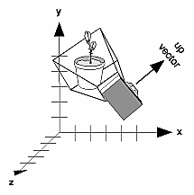
Figure 3-11 : Default Camera Position Figure 3-12 shows the effect of a typical gluLookAt() routine. The camera position (eyex, eyey, eyez) is at (4, 2, 1). In this case, the camera is looking right at the model, so the reference point is at (2, 4, -3). An orientation vector of (2, 2, -1) is chosen to rotate the viewpoint to this 45-degree angle.
Figure 3-12 : Using gluLookAt() So, to achieve this effect, call gluLookAt(4.0, 2.0, 1.0, 2.0, 4.0, -3.0, 2.0, 2.0, -1.0); Note that gluLookAt() is part of the Utility Library rather than the basic OpenGL library. This isn't because it's not useful, but because it encapsulates several basic OpenGL commands - specifically, glTranslate*() and glRotate*(). To see this, imagine a camera located at an arbitrary viewpoint and oriented according to a line of sight, both as specified with gluLookAt() and a scene located at the origin. To "undo" what gluLookAt() does, you need to transform the camera so that it sits at the origin and points down the negative z-axis, the default position. A simple translate moves the camera to the origin. You can easily imagine a series of rotations about each of the three axes of a fixed coordinate system that would orient the camera so that it pointed toward negative z values. Since OpenGL allows rotation about an arbitrary axis, you can accomplish any desired rotation of the camera with a single glRotate*() command. Note: You can have only one active viewing transformation. You cannot try to combine the effects of two viewing transformations, any more than a camera can have two tripods. If you want to change the position of the camera, make sure you call glLoadIdentity() to wipe away the effects of any current viewing transformation. Advanced To transform any arbitrary vector so that it's coincident with another arbitrary vector (for instance, the negative z-axis), you need to do a little mathematics. The axis about which you want to rotate is given by the cross product of the two normalized vectors. To find the angle of rotation, normalize the initial two vectors. The cosine of the desired angle between the vectors is equal to the dot product of the normalized vectors. The angle of rotation around the axis given by the cross product is always between 0 and 180 degrees. (See Appendix E for definitions of cross and dot products.) Note that computing the angle between two normalized vectors by taking the inverse cosine of their dot product is not very accurate, especially for small angles. But it should work well enough to get you started. Creating a Custom Utility RoutineAdvanced For some specialized applications, you might want to define your own transformation routine. Since this is rarely done and in any case is a fairly advanced topic, it's left mostly as an exercise for the reader. The following exercises suggest two custom viewing transformations that might be useful. Try This
Show that the following routine could serve as the viewing transformation: void pilotView{GLdouble planex, GLdouble planey,
GLdouble planez, GLdouble roll, GLdouble pitch, GLdouble heading) {
glRotated(roll, 0.0, 0.0, 1.0); glRotated(pitch, 0.0, 1.0, 0.0); glRotated(heading, 1.0, 0.0, 0.0); glTranslated(-planex, -planey, -planez); }
Show that the following routine could serve as the viewing transformation: void polarView{GLdouble distance, GLdouble twist,
GLdouble elevation, GLdouble azimuth) {
glTranslated(0.0, 0.0, -distance); glRotated(-twist, 0.0, 0.0, 1.0); glRotated(-elevation, 1.0, 0.0, 0.0); glRotated(azimuth, 0.0, 0.0, 1.0); } |
Програмирование с использованием OpenGL